
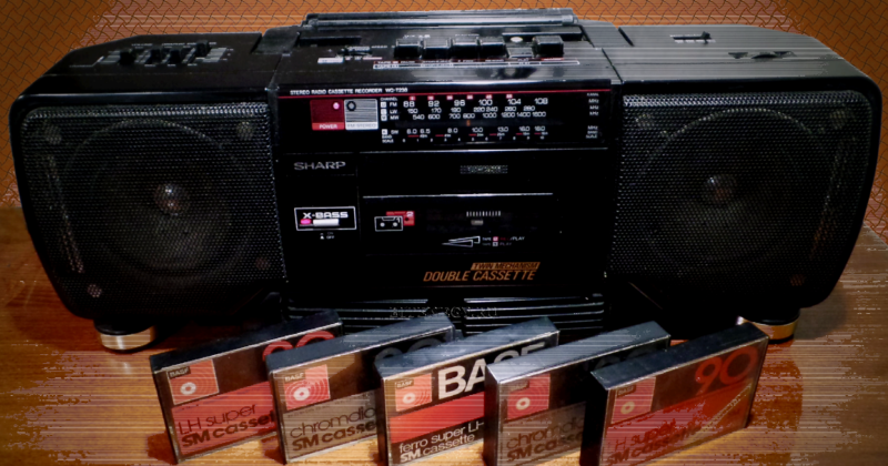
The history of this work lasts from open spaces of the modern Internet in nostalgia according to the magnetic record of the last century. Came across somehow at himself in a cushion a pile of the old cartridges which lay without need it is a lot of years. It was decided to get the old Sharp who did not bad to maintain the shape, to wipe heads with cologne and to include “memoirs”. Yes, I hung up at several o’clock, driving to and fro old records. Nostalgia created a rare question in we wash an inquisitive brain – you have an Internet where all music is collected, and under it someone opens a mouth for what to you this old material? Well … yes, in global network it is possible to see big sets of tape recorders. Well … yes, got into a wide area network, it appears, the whole museums of tape recorders at people. Huge collections, worthy the former audio of shops are collected. Sparkling on shelves of Sony’s, Panasonic’s and Sharp’s filled with deep-voices tunes space around “collector”. Likely and this field of activity is not so useless, I thought, besides rare models can be brought with confidence to the level of the work of art, such top of a design thought of the past. Laudatory odes of “analog recording” can be seen in posts and at the forums devoted to tape recorders. Thereby, the market of tape recorders continues to live. In the past I took part in developments of the similar equipment in the twilight of the magnetophonobuilding, and the circuitry of these products is not bad familiar to me. But there is a strong feeling that it is just nostalgia, and we are made a fool, pushing the pipes of gramophone rubbed to gloss and lulling memories of the light passed. Anyway, I decided to find out how analog recording really is analog? To someone formulas and details of technical character aren't interesting, conclusions at the end of this work.
Let's provide amplitude as any function on time, then function of amplitude:
Let's consider randomly the changing signal (Fig. 1), and we will select from it the section of time of ∆t which has dimension of time of quantization of a digital signal, we will not penetrate now into identity of this section since it can be any quantum of a signal.
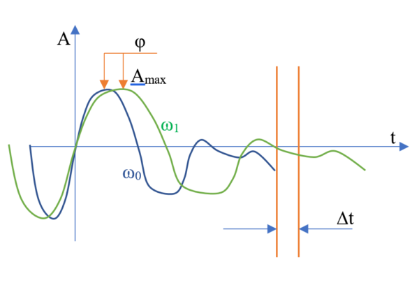
Figure 1 Schedule of the difference of frequencies
If ∆t is so a little that the segment cut on function can be taken for linear, then the function graph (1) on this section has:
-
1) Increase;
2) Decrease;
3) Horizontal section.
The relation of inclinations of characteristics of two neighboring sections of function cannot exceed some constant because the frequency range of a path of record playback is limited on top to technical capabilities. Restriction of frequency range from below gives impossibility of long existence of the section (3). In essence, the inclination of characteristic is a derivative of function in a point (A, t) our diagram. The greatest possible inclination of characteristic is defined by the greatest possible frequency rate of a path of record playback, we will call it as (ω_{max}). For a path of record playback the minimum signal amplitude corresponds to Boolean function of single jump of a signal:
The module of amplitude indicates tolerance of positive and negative half waves. Then, the maximum amplitude we can present the sums of the minimum jumps in the form:
Values of shift of the phase (φ) of the pica of the signal (A_{max}) in the point (\pi), two close frequencies, differ with manifestation of the single signal (bit) which appears with the smaller frequency. As amplitude (A_{max}) same, function of single amplitude of the sine signal for higher frequency, lags behind on the corner (φ). Amplitude of single jump of the signal:
This formula is very remarkable what amplitude of(A_{max} \ge A_{min} )we would not try to write down at the maximum frequency (\omega_{max}), for the tape of signal frequency, at the exit we will receive only one value equal to the minimum bit of the signal as limiting frequency is initially accepted to the minimum level of the signal at the exit:
Let's define the delta of frequencies as the module of the difference maximum at which amplitude of record of the signal not the otlichima from noise of the sound path and the tape and limit, showing stable bit:
We determine amplitude of the bit step:
As frequencies with which the bit of information of the analog signal relatives is formed, the relation of points of time, are equal. The second condition (F.2) defines equally likely option of record of zero and single bit.
From the schedule of the noise component one is allocated two sites, with the maximum frequency, the second with the minimum change of signal amplitude from the flat site of the curve, we obtain data for calculations. The site of measurement of frequency is chosen as lasting 500 microsec. It is the threshold of reaction of hearing to change of the front of the attack, or recession of the signal. The theory is based on differential sensitivity of the auditory organ. For deleting of the tape, the tape recorder is transferred to the CrO_2 mode (chromium oxide) as the erasing current is more. Record of the peak signal was made with use of the simplest generator program on the basis of the sound card of the computer of own development (it will be uploaded to the website). As the measuring system at first the analog oscillograph, but as it turned out was used, the program way of measurement of sound characteristics of the tape recorder gives similar results. The sound card with 24 bit ACP completely blocks the needs for similar measurements.
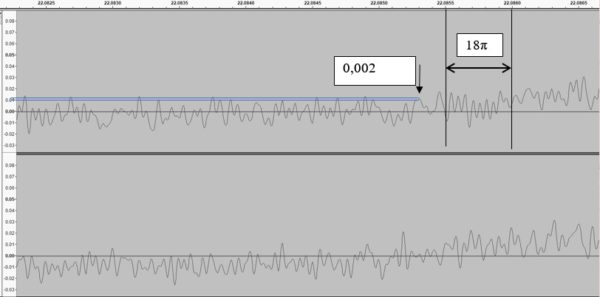
The schedule of noise of the erased tape
From the schedule of noise and the maximum amplitude of experimental Sharp we receive the maximum frequency:
It should be noted that we do not become attached to standards, and look for practical result on the basis of which describe digital transformation including at the minimum levels of a signal where the frequency of record is greatest possible. Also we will note that we operate with amplitude in conventional units (c.u). Level of loudness does not change at measurements, and as loading serves active nominal resistance. Frequency of sampling of one channel of Sharp has to be above the second harmonica of the maximum frequency of reproduction, and the sound path is provided with the filter of low frequencies which is present at circuitry of the tape recorder:
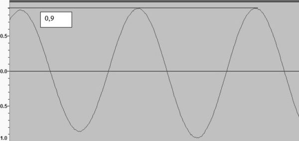
Schedule of the maximum amplitude
Dynamic range is bounded above overload capacity of the tape. Write amplifiers are supplied with level limiters which prevent the tape overload. We determine the bit depth of the analog path as:
The two is the scope of amplitudes. Compander squelch can expand the dynamic range, but not the bit depth of the system. It depends on circuitry of devices. Only the amplitude of the (A_{min}), bit step is increased. By the way, characteristic distortions of systems of noise reduction are the consequence of increase in amplitude of the bit step. And so a moment of truth:
Сonclusions:
Copyright © Aleksei Tarasov (Bit depth of the old tape recorder) 2019